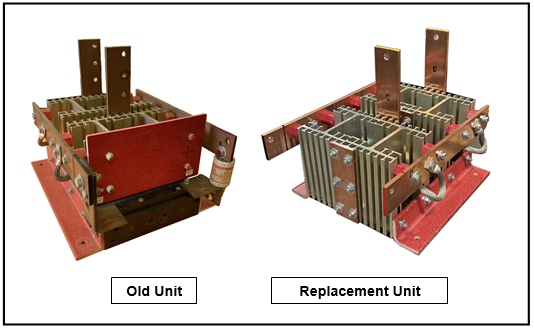
A diode bridge assembly, often referred to as a bridge rectifier, is a crucial component in electronics that converts alternating current (AC) into direct current (DC). If you need to replace a diode bridge assembly, you can follow these general steps:
-
Identify the Faulty Bridge Rectifier: First, determine which diode bridge assembly is faulty. This might require some troubleshooting and testing to identify the problematic component.
-
Turn Off Power: Before doing any replacement or repair work, make sure to turn off the power source to the circuit or device where the bridge rectifier is located. This is essential for your safety.
-
Locate the Diode Bridge Assembly: Find the diode bridge assembly on your circuit board or within your electronic device. It is usually a small square or rectangular component with four diodes arranged in a bridge configuration.
-
Desolder the Old Diode Bridge Assembly:
- Use a soldering iron to heat and melt the solder joints on the diode leads.
- Carefully remove the old diode bridge assembly from the circuit board.
-
Prepare the Replacement: Ensure that you have a suitable replacement diode bridge assembly. It should have the same electrical specifications as the original (e.g., voltage and current ratings).
-
Solder the New Diode Bridge Assembly:
- Align the replacement diode bridge assembly in the same orientation as the old one.
- Solder the leads to the appropriate locations on the circuit board.
-
Inspect the Solder Joints: After soldering, inspect the solder joints to ensure they are clean and secure. Make sure there are no solder bridges between adjacent leads.
-
Reconnect the Power: After verifying that the new diode bridge assembly is securely in place and properly soldered, reconnect the power source to the circuit or device.
-
Test the Circuit: Turn on the power and test the circuit to ensure that the replacement diode bridge assembly is functioning correctly. Use a multimeter or other testing equipment to verify the output voltage and current.
-
Secure and Close: If everything is working as expected, secure any fasteners or covers, and close the device or circuit enclosure.
Please note that these steps are a general guideline, and the specifics may vary depending on the type of circuit or device you are working on. Always follow safety precautions and refer to the manufacturer’s documentation or service manuals for specific guidance if available. If you’re not confident in your soldering and electronics repair skills, it’s advisable to seek assistance from a professional technician or repair service.

