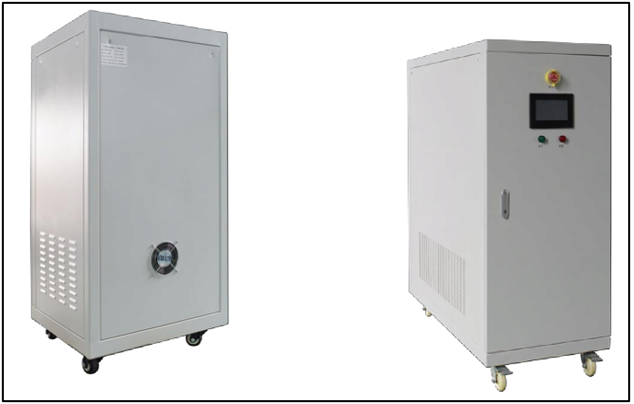
Designing a DC to AC inverter with a power output of 10 kW to 30 kW using IGBT (Insulated Gate Bipolar Transistor) technology is a complex engineering project that requires a deep understanding of power electronics, control systems, and circuit design. Here is a high-level overview of the key steps and considerations involved in designing such an inverter:
-
Specifications and Requirements:
- Define the specific requirements for your inverter, including the input voltage range, output voltage and frequency, efficiency, and any other special features or constraints.
-
Topology Selection:
- Choose the appropriate inverter topology, such as a voltage-source inverter (VSI) or a current-source inverter (CSI), based on your requirements. For most high-power applications, a VSI is common.
-
Components Selection:
- Select high-power IGBT modules that can handle the desired power range. Ensure the selected IGBTs have the necessary voltage and current ratings.
- Choose appropriate capacitors, diodes, and other passive components.
-
DC Link Capacitor:
- Design the DC link capacitor to provide smooth DC voltage and handle high ripple current.
-
Gate Drivers:
- Implement IGBT gate drivers to properly control the switching of IGBTs. Make sure gate driver specifications match the IGBTs.
-
Control System:
- Develop a control system that includes PWM (Pulse Width Modulation) control to generate the AC output voltage and frequency.
- Implement overcurrent protection, overvoltage protection, and other safety features.
-
Cooling System:
- A high-power inverter generates heat, so an efficient cooling system is crucial. Consider using forced air cooling, liquid cooling, or a combination of both.
-
Protection and Safety:
- Implement various protection mechanisms to safeguard the inverter and connected loads. This includes overcurrent protection, short-circuit protection, and overtemperature protection.
-
Isolation:
- Ensure proper isolation between the DC and AC sides of the inverter using isolation transformers or optocouplers.
-
Testing and Simulation:
- Simulate the inverter’s performance using software tools like SPICE or specialized power electronics simulation software.
- Test the physical inverter in a controlled environment to verify its performance and safety.
- Efficiency Optimization:
- Optimize the design for maximum efficiency by selecting high-quality components and minimizing losses in the system.
- EMI/RFI Compliance:
- Ensure that the inverter design complies with electromagnetic interference (EMI) and radio-frequency interference (RFI) standards.
- Compliance and Certification:
- Depending on the application, the inverter may need to pass certain safety and quality certifications.
- Documentation and Manuals:
- Create comprehensive documentation and user manuals for installation, operation, and maintenance.
- Scaling and Customization:
- Consider how to scale the design to different power levels or customize it for specific applications.
It’s important to note that designing a high-power inverter like this is a complex task and often requires a team of electrical engineers and resources. Additionally, you may want to consult with or hire an experienced power electronics engineer to ensure the design meets safety, efficiency, and reliability standards.

