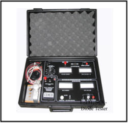
Testing a Silicon Controlled Rectifier (SCR) or a diode requires a few basic tools and methods to ensure they are functioning correctly. Here’s how you can test them:
Testing a Diode:
-
Turn Off Power: Ensure that the diode is not connected to any power source before testing.
-
Set Your Multimeter: Set your multimeter to the “diode test” mode, which is often represented by a diode symbol on the selector dial.
-
Diode Orientation: Identify the cathode (negative) and anode (positive) terminals of the diode. The cathode is usually marked with a band or a line.
-
Test the Diode:
- Place the red probe (positive) on the anode side of the diode.
- Place the black probe (negative) on the cathode side.
- Read the multimeter display. If the diode is functional, it should display a voltage drop of around 0.6 to 0.7 volts for a silicon diode. If the multimeter displays “OL” or a high resistance value, it means the diode is open (not working). If it displays a very low resistance value in both directions, the diode may be shorted.
-
Reverse the Probes: Swap the probes’ positions (red on cathode, black on anode) and repeat the test. In this case, you should see a high resistance value or “OL” on the multimeter, indicating that the diode is not conducting in reverse bias.
Testing an SCR (Silicon Controlled Rectifier):
-
Turn Off Power: Ensure that the SCR is not connected to any power source before testing.
-
Set Your Multimeter: Set your multimeter to the “diode test” mode as described above.
-
SCR Pins: Identify the three pins of the SCR: Anode (A), Cathode (K), and Gate (G). The gate is usually the smaller pin or has a distinctive marking.
-
Test the SCR:
- Place the red probe (positive) on the anode (A) of the SCR.
- Place the black probe (negative) on the cathode (K) of the SCR.
- You should see a high resistance value or “OL” on the multimeter, indicating that the SCR is not conducting in this direction.
-
Test the Gate: While keeping the red probe on the anode (A), move the black probe to the gate (G).
- In one direction, you should see a high resistance value or “OL,” indicating that the SCR is not conducting when the gate is not triggered.
- In the other direction, you should see a low resistance value, indicating that the SCR is conducting when the gate is triggered.
Testing an SCR may also involve more comprehensive tests to ensure its proper functioning in a circuit, including triggering the gate with a controlled voltage signal, but the basic diode test can help you determine if the SCR is functional or not.
Always consult the datasheet or specifications for the specific SCR or diode you are testing, as some devices may have different characteristics or testing procedures.

